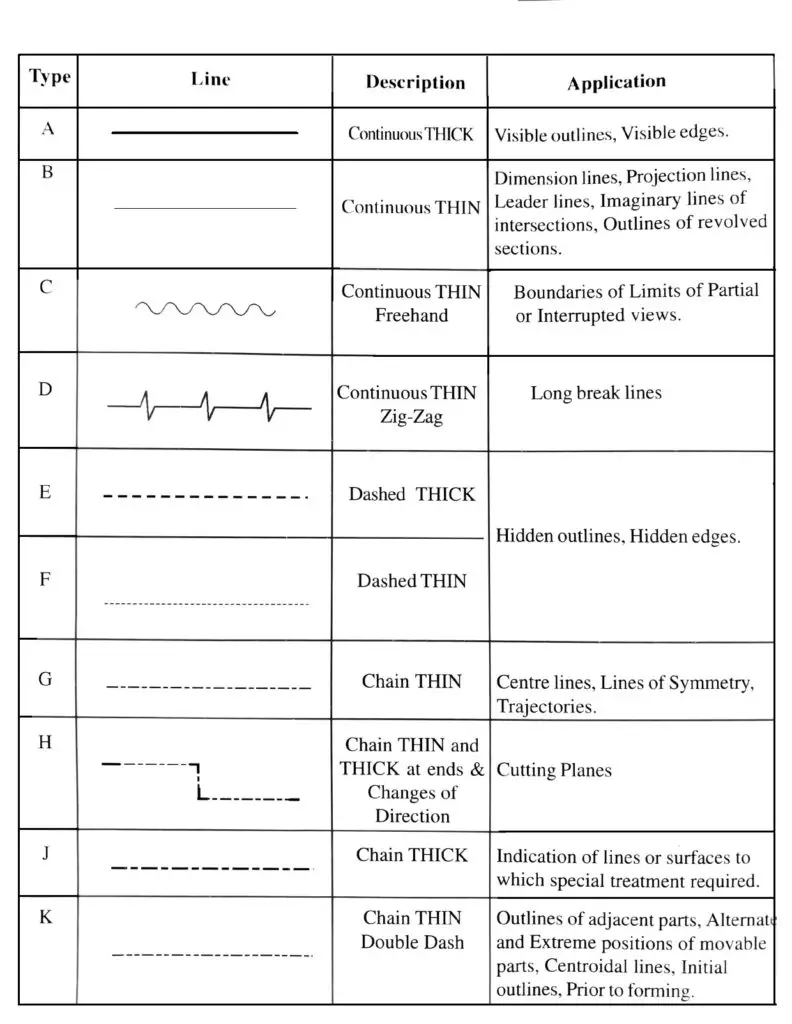
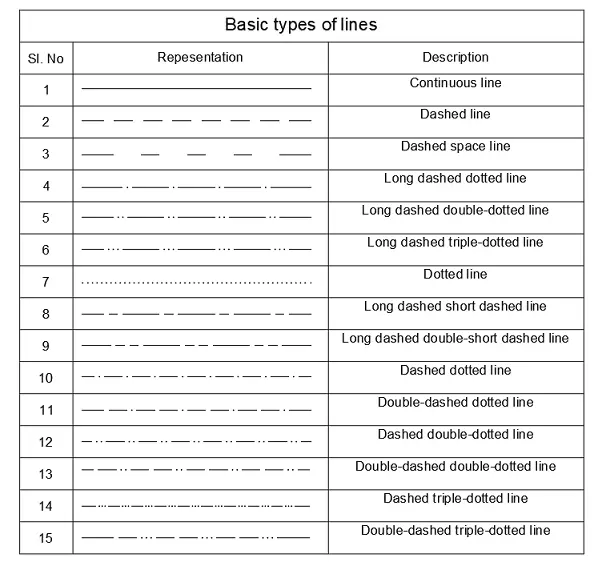
What Are The Different Views Of Lines Used In Engineering Drawings For general engineering drawings the types of lines recommended by the Bureau of Indian Standards shown in Table 2 must be used The thickness of the lines must be chosen according to the type and size of the drawing from any of the six groups given in Table 1 Following are the different types of lines used in engineering drawing A type
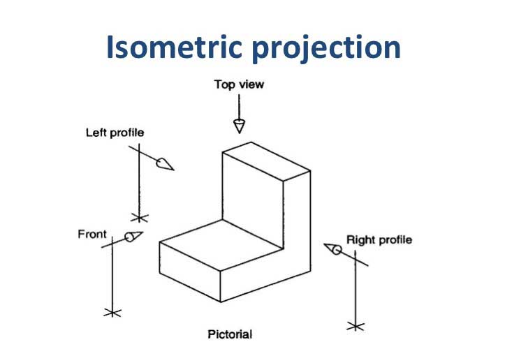
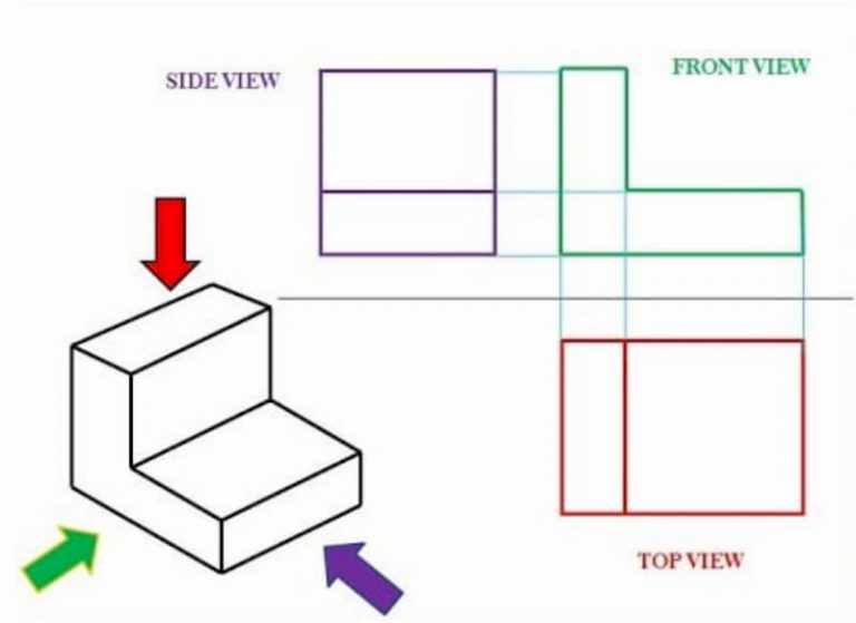
Improve the clarity and organization of engineering drawings by visually connecting notes and labels to relevant elements Orthographic Projection Lines Demystified Definition Orthographic projection lines are used in engineering and technical drawings to create multiple 2D views of a 3D object These lines represent the direction of view and Precedence of Lines When different types of lines overlap or intersect in a technical drawing a specific hierarchy is followed to prioritize visibility and importance This is called the Precedence of Lines The general rule is 1 Visible Object Lines Highest Priority Always take precedence over other lines
What Are The Different Views Of Lines Used In Engineering Drawings

What Are The Different Views Of Lines Used In Engineering Drawings
https://i.ytimg.com/vi/7B4bjCr91b4/maxresdefault.jpg

CivilSeek Everything You Need To Know About Civil Engineering
https://civilseek.com/wp-content/uploads/2018/10/isometric-projection-.jpg

Orthographic Drawings Autocad Drawing Technical Drawing Orthographic
https://i.pinimg.com/originals/47/61/ad/4761adfd1d97317fe42d1d16363e7504.jpg
The dashed line may be either thick or thin but only one type thick or thin should be used on a single drawing or set of drawings Thin Chain Line The Thin Chain Line is used to indicate center lines the lines of symmetry and also trajectories Often this line is used as a point of reference on engineering drawings Thin Chain Line with The Purpose of Engineering Drawings As already said such a technical drawing has all the information for manufacturing a part or welding and building an assembly The info includes dimensions part names and numbers etc So once a manufacturing engineer gets the drawing he can start the production process without a second thought
Different Types of Lines Used in Technical Drawings Visible Lines Object Lines Represent the actual shape and edges of an object Drawn as thick solid continuous lines Hidden Lines Show internal features or edges that are not visible in a specific view Drawn as thin dashed lines Center Lines A miter lines are unique type of technical or engineering drawing lines mainly used to transfer depth dimension s of an object between the object s top or plan view and its right side view in a multiview drawing or two different parts of different drawings Stitch lines comprise of a series of very short dashes that are evenly spaced
More picture related to What Are The Different Views Of Lines Used In Engineering Drawings

Teknik
https://i.ytimg.com/vi/2iPXRV0C1FA/maxresdefault.jpg

10 Different Types Of Lines Used In Engineering Drawing Types Of Lines
https://www.theengineerspost.com/wp-content/uploads/2020/12/Scan-07-Dec-2020_page-0001-792x1024.jpg

INCH Technical English Pictorial Engineering Drawing Line Types
https://inchbyinch.de/wp-content/uploads/2021/02/0653-line-types-1536x1152.jpeg
Without different views engineering drawings cannot exist so understanding how views are used on drawings is a critical Different views Base views Projected views Sectional views Auxiliary views An arrow is used to identify the surface that is looked at Ideally the view that is created should be shown in line with the direction of 1 Projection Lines The prevalent form is a continuous line also referred to as a Projection line which signifies the tangible boundaries of an object Projection lines project points from the object onto the drawing plane 2 Hidden Lines Hidden lines represent features obstructed from view 3 Centerlines Centerline serve the purpose of indicating holes and the axis or symmetry of
[desc-10] [desc-11]

Engineering Drawing Views Basics Explained Fractory
https://fractory.com/wp-content/uploads/2020/06/orto-1-1-768x559.jpg

Drafting Line Types
https://qnaengine.com/wp-content/uploads/2021/03/types-of-lines.png
What Are The Different Views Of Lines Used In Engineering Drawings - Different Types of Lines Used in Technical Drawings Visible Lines Object Lines Represent the actual shape and edges of an object Drawn as thick solid continuous lines Hidden Lines Show internal features or edges that are not visible in a specific view Drawn as thin dashed lines Center Lines